ASSEMBLE spyndra hardware
1. PLACE HEAT INSERTS & MAGNETS INTO CHASSIS
- 4 large heat inserts into Chassis side using soldering iron
- 4 large heat inserts into Tibia side
- 4 small heat inserts into Chassis body for Raspberry Pi
- 2 small heat inserts for Battery Charger
- Glue Chassis magnets to secure connection with Spyndra Top
2. ASSEMBLE FEMUR WITH CHASSIS (REPEAT FOR ALL 4 FEMURS)
- Pressfit Motor into Tibia
- Secure Motor with 2 Screws (from Motor package)
- Servo Horn Calibration
- Using Servo Horn, turn Motor to end of travel limit
- Put on calibration jig
- Place Servo Horn according to calibration jig
- Secure Servo Horn
- Secure Femur
- Repeat for all 4 Femurs
3. ASSEMBLE TIBIA WITH FEMUR
- Insert Low-Friction Sleeve Bearing into Femur
- Servo Horn Calibration
- Using Servo Horn, turn Motor to end of travel limit
- Put on calibration jig
- Place Servo Horn according to calibration jig
- Secure Servo Horn
- Secure Servo Arm
- Slide secured Servo Arm into Femur
- Secure Tibia with Shoulder Bolt
- Repeat for all 4 Tibias and Femurs
Assemble Chassis with Electronics
4. Assemble Electronics Onto Chassis
- Assemble PowerBoost 1000 Charger
- Solder black wire into ground, make sure other end of wire is female
- Solder red wire into +5V, make sure other end of wire is female
- Screw charger into chassis
- IMU
- Insert heat sets in designated area under Raspberry Pi
- Solder pins to SDA, SCL, 3 Volts, GND on IMU
- Solder pins to 3V and GND on top right of RPi Hat
- Screw in IMU
- Wire IMU to RPi Hat at SDA, SCL 3 Volts and GND
- Solder Raspberry Pi Hat
- Solder GPIO adapter pins to RPi Hat to plug into Raspberry Pi
- Solder motor header pins to RPi Hat for motors to plug in
- Solder capacitor into center (check polarity)
- Solder blue terminal block into ground and 5V
- Solder pins for SDA and SCL ports (top right corner)
- Place tape on Raspberry Pi to prevent short-circuiting
- LiPo Battery
- Insert blue attachment to RPi Hat (left edge)
- Secure a positive and ground lead with female adapters to blue attachment
- Insert LiPo in bay under Chassis and connect to power leads
- Adhere LiPo Voltage Alarm to side of LiPo bay and attach leads
- LiPo will have to be removed and charged separately from Li-Ion when low
- Make sure to keep LiPo within recommended voltages
- Connecting Electronics to Chassis
- Screw in Battery Charger
- Screw in Raspberry Pi
- Attach RPi Hat to Raspberry Pi
- Li-ION battery plugs into PowerBoost 1000 and fits snugly on opposite side of RPi (from charger)
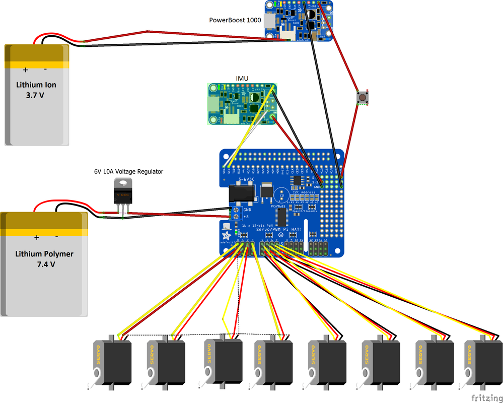
6. Plugging in Motors & Batteries
- Plug each Motor into Arduino hat
- Place Battery into Chassis